Operating Principle of DC Motor
A DC motor in simple words is a device that converts direct current(electrical energy) into mechanical energy. It’s of vital importance for the industry today, and is equally important for engineers to look into the working principle of DC motor in details that has been discussed in this article. In order to understand the operating principle of dc motor we need to first look into its constructional feature.
The very basic construction of a dc motor contains a current carrying armature which is connected to the supply end through commutator segments and brushes and placed within the north south poles of a permanent or an electro-magnet as shown in the diagram below.
Now to go into the details of the operating principle of DC motor its important that we have a clear understanding of Fleming’s left hand rule to determine the direction of force acting on the armature conductors of dc motor. 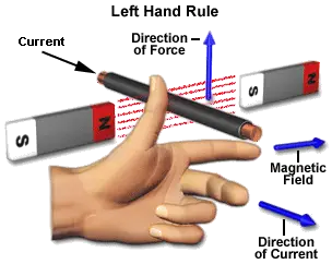 Fleming’s left hand rule says that if we extend the index finger, middle finger and thumb of our left hand in such a way that the current carrying conductor is placed in a magnetic field (represented by the index finger) is perpendicular to the direction of current (represented by the middle finger), then the conductor experiences a force in the direction (represented by the thumb) mutually perpendicular to both the direction of field and the current in the conductor.
For clear understanding the principle of DC motor we have to determine the magnitude of the force, by considering the diagram below.
We know that when an infinitely small charge dq is made to flow at a velocity ‘v’ under the influence of an electric field E, and a magnetic field B, then the Lorentz Force dF experienced by the charge is given by:- 

Then the force on the left hand side armature conductor,


Now let’s examine the expression of torque when the armature turn crate an angle of α with its initial position.
The torque produced is given by,

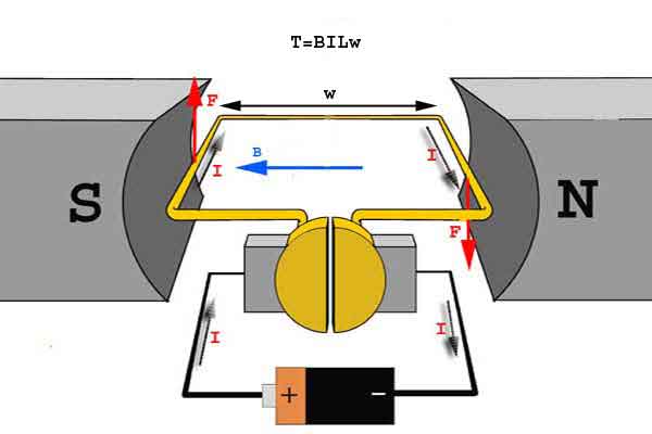
The presence of the term cosα in the torque equation very well signifies that unlike force the torque at all position is not the same. It in fact varies with the variation of the angle α. To explain the variation of torque and the principle behind rotation of the motor let us do a step wise analysis. 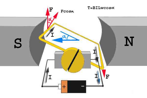 Step 1: Initially considering the armature is in its starting point or reference position where the angle α = 0.

 Step 2: Once the armature is set in motion, the angle α between the actual position of the armature and its reference initial position goes on increasing in the path of its rotation until it becomes 90° from its initial position. Consequently the term cosα decreases and also the value of torque.
The torque in this case is given by τ = BILwcosα which is less than BIL w when α is greater than 0°.

Step 3: In the path of the rotation of the armature a point is reached where the actual position of the rotor is exactly perpendicular to its initial position, i.e. α = 90°, and as a result the term cosα = 0.
The torque acting on the conductor at this position is given by,

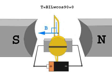
i.e. virtually no rotating torque acts on the armature at this instance. But still the armature does not come to a standstill, this is because of the fact that the operation of dc motor has been engineered in such a way that the inertia of motion at this point is just enough to overcome this point of null torque. Once the rotor crosses over this position the angle between the actual position of the armature and the initial plane again decreases and torque starts acting on it again.