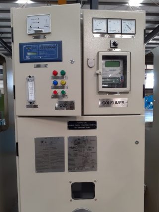
Switch Gear:
The apparatus used for controlling, regulating and switching on or off the electrical circuit in the electrical power system is known as switch gear. It also includes the combination of switching devices with associated control, measuring, protecting and regulating equipment. The switch gear devices and their assemblies are used in connection with the generation, transmission, distribution, and conversion of electrical energy. We all are familiar with low voltage switches and re-wireable fuses in our homes. Switches are used for opening and closing an electric circuit while fuses are used for over-current and short circuit protection. In such a way, every electrical device wants a switching and a protecting device. Various forms of switching and protective devices have been developed. Thus, switch gear can be taken as a general term covering a wide range of equipment concerned with the switching, protection, and control of various electrical equipment.
The main functions of switch gear are,
:• Electrical protection
• Electrical isolation of sections of an installation
• Local or remote switching
• Electrical protection in Switch Gear:
The aim is to avoid or to limit the destructive or dangerous consequences of excessive (short circuit) currents, or those due to overloading and insulation failure, and to separate the defective circuit from the rest of the installation. A distinction is made between the protection of:
• The elements of the installation (cables, wires, switch gear…)
• Persons and animals
• Equipment and appliances supplied from the installation
The protection of circuits
• Against overload; a condition of excessive current being drawn from a healthy (unfaulted) installation.
• Against short-circuit currents due to complete failure of insulation between conductors of different phases or (in TN systems) between a phase and neutral (or PE) conductor.
Protection in these cases is provided either by fuses or circuit-breaker, in the distribution board at the origin of the final circuit (i.e. the circuit to which the load is connected).
The protection of persons
• Against insulation failures. According to the system of earthing for the installation (TN, TT or IT) the protection will be provided by fuses or circuit-breakers, residual current devices, and/or permanent monitoring of the insulation resistance of the installation to earth.
The protection of electric motors
• Against overheating, due, for example, to long term overloading, stalled rotor, single-phasing, etc. Thermal relays, specially designed to match the particular characteristics of motors are used.
Such relays may, if required, also protect the motor-circuit cable against overload. Short-circuit protection is provided either by type aM fuses or by a circuit-breaker from which the thermal (overload) protective element has been removed, or otherwise made inoperative.
• Isolation
The aim of isolation is to separate a circuit or apparatus (such as a motor, etc.) from the remainder of a system which is energized, in order that personnel may carry out work on the isolated part in perfect safety.
An isolating device must fulfill the following requirements:
• All poles of a circuit, including the neutral (except where the neutral is a PEN conductor) must open. • It must be provided with a locking system in open position with a key (e.g. by means of a padlock) in order to avoid an unauthorized reclosure by inadvertence
• It must comply with a recognized national or international standard (e.g. IEC 60947-3) concerning clearance between contacts, creepage distances, over voltage withstand capability, etc.
• Switching
In broad terms “control” signifies any facility for safely modifying a load-carrying power system at all levels of an installation. The operation of switchgear is an important part of power-system control.
Functional control
This control relates to all switching operations in normal service conditions for energizing or de-energizing a part of a system or installation, or an individual piece of equipment, item of plant, etc.
Switch gear intended for such duty must be installed at least:
• At the origin of any installation
• At the final load circuit or circuits (one switch may control several loads)
Emergency switching – emergency stop
An emergency switching is intended to de-energize a live circuit which is, or could become, dangerous (electric shock or fire). An emergency stop is intended to halt a movement which has become dangerous.
In the two cases:
• The emergency control device or its means of operation (local or at remote location(s)) such as a large red mushroom-headed emergency-stop push button must be recognizable and readily accessible, in proximity to any position at which danger could arise or be seen.
• A single action must result in a complete switching-off of all live conductors
• A “break glass” emergency switching initiation device is authorized, but in unmanned installations the re-energizing of the circuit can only be achieved by means of a key held by an authorized person.
It should be noted that in certain cases, an emergency system of braking, may require that the auxiliary supply to the braking-system circuits be maintained until final stoppage of the machinery.
Switching-off for mechanical maintenance work
This operation assures the stopping of a machine and its impossibility to be inadvertent restarted while mechanical maintenance work is being carried out on the driven machinery. The shutdown is generally carried out at the functional switching device, with the use of a suitable safety lock and warning notice at the switch mechanism.
Read more about Switch Gears
